Choosing automotive wire is not just a matter of matching colors or buying the thickest cable on the shelf. The right choice depends on current load, circuit length, temperature, and where the wire will run. A cable routed beside a hot engine needs different protection from one tucked behind a dashboard. Small details matter. A wire that looks suitable may still overheat, chafe, or become brittle if its insulation does not suit the environment.
This guide explores ten practical considerations for selecting automotive wire, from gauge and insulation type to flexibility, routing, and connector compatibility. Check the vehicle manufacturer’s specifications whenever possible, and account for voltage drop on longer runs. Bundled wires can also retain heat, so a rating that works for a short, exposed cable may not work in a crowded harness. It is easy to focus on the wire itself and overlook the terminals or protective sleeving around it. That is a common weak spot. Reliable choices come from checking the whole circuit, not guessing from appearance alone. The right approach may take an extra measurement or a second look at the service information. That time is usually worthwhile.
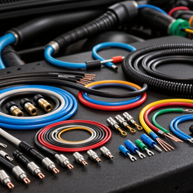
Before choosing automotive wire, estimate the circuit’s actual current draw, not just the load’s advertised wattage. For a resistive load, current is approximately power divided by voltage; motors and pumps may draw much more during startup. Check whether several devices can run at once. Small details matter. A 12-volt circuit feeding a lamp through a long run may need a heavier wire than the same lamp mounted nearby, because the current travels out and back.
Next, compare the expected current with a wire ampacity chart, then account for voltage drop and installation conditions. A dashboard accessory and an engine-bay component face different heat, vibration, and bundling. Those conditions can reduce a wire’s safe current capacity. Use the vehicle or component specifications where available, and choose insulation rated for the location. It is tempting to trust a gauge chart alone; that can be a mistake. Charts rely on assumptions about temperature and installation. Check the full wire length, including the return path, and size the fuse to protect the wire. If your measurements are uncertain, pause and verify them before cutting.
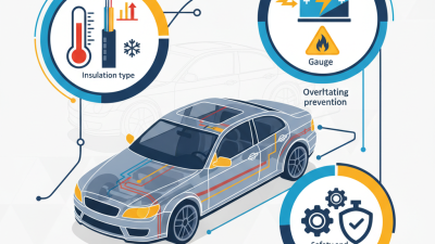
Choosing wire gauge starts with current, circuit length, and acceptable voltage drop. A thicker conductor has lower resistance, but the correct size depends on how the wire is installed. Bundled cables and hot engine bays can retain heat. Check the fuse, too. It protects the wire, not just the device.
The Copper Development Association lists annealed copper conductivity at 100% IACS, about 58 MS/m at 20°C. Yet even copper wire can lose useful voltage over a long run. Using standard AWG resistance data, a 20-foot round trip of 16-AWG copper drops about 0.8 volts at 10 amps, before accounting for heat. On a 12-volt circuit, that is roughly 6.7%. SAE International’s J1128 standard sets construction and performance requirements for low-voltage automotive primary cable; it is a useful reference, not a substitute for calculating the actual circuit.
Measure the full path, including the return wire, then check a current-capacity table for the insulation temperature and installation conditions. I would not size from a short online chart alone. The chart may assume open air, while your wire sits inside a tight loom beside a warm engine. That shortcut can be wrong. Recheck voltage drop after installation, especially if lights dim or a connector feels warm. A little extra copper may help, but an oversized fuse will not.
Choosing automotive wire starts with the insulation, not just the copper size. Check the temperature rating against the wire’s actual location. Under a hood, radiant heat from an engine or exhaust can soften an unsuitable jacket. In a cabin, lower heat may still meet moisture, abrasion, or chemical exposure. Read the product data sheet; a temperature number alone does not describe every condition.
Tip: Match the rating to the hottest expected environment, then allow a margin. Check whether the listed rating applies to continuous use or a brief peak. A wire bundled tightly with others may run hotter than one in open air. I have seen this detail overlooked on tidy-looking harnesses. Neat routing is not enough.
Look for insulation suited to the specific exposure: heat, oil, fuel vapor, water, or repeated movement. A jacket that resists heat may not resist abrasion well. Secure wire away from sharp edges and hot surfaces, and use suitable protection where contact is possible. Do not choose by color or appearance alone. Confirm the temperature rating, insulation type, and conductor size together. If the installation details are uncertain, pause and verify them; guessing is easy, and not always harmless.
Match insulation and temperature ratings to the application.
Typical maximum continuous temperature ratings are shown for comparison: general-purpose PVC is commonly rated at 80°C, high-temperature PVC at 105°C, cross-linked polyolefin at 125°C, and silicone rubber at 150°C. Ratings vary by wire construction and specification; verify the applicable standard and account for the temperature near the installed wire.
Tip: Map the route before selecting insulation. Record heat near exhaust parts, oil mist, road salt, cleaning fluids, and moisture under trim. Conditions can change over a few centimeters. A wire that feels flexible on a workbench may stiffen or crack after repeated heat cycles. Check the expected temperature where the wire actually runs, not just the general engine-bay rating.
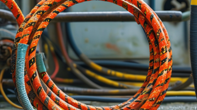
Tip: Look for rubbing points and movement. Inspect sharp brackets, panel edges, tight bends, and places where the harness vibrates against the body. Use suitable grommets, clamps, or abrasion-resistant sleeving where contact is likely. Leave enough slack for engine movement, but avoid loose loops that can snag. Small details matter. A protective sleeve can help, yet it may also hold moisture if poorly fitted.
Tip: Match protection to the conditions, then inspect the finished route. Confirm that clips stay secure and insulation does not flatten at bends. Where measurements are unavailable, allow a safety margin and verify the wire’s temperature and fluid resistance with its specifications. I would not assume extra wrapping is always safer; trapped grit or water can cause problems too. Recheck after the first period of operation.
Choosing automotive wire starts with the conductor, insulation, and the conditions under the hood. The Copper Development Association lists annealed copper at 100% IACS conductivity; aluminum is about 61%. That difference affects conductor size and connection design. Check the wire’s temperature, voltage, abrasion, and fluid-resistance ratings against its actual route. A matching gauge alone is not enough. It is tempting to stop there.
Standards help narrow the choice. SAE J1128 covers low-voltage primary cable for road vehicles; confirm the applicable edition and vehicle requirements before buying. The IEA’s Global EV Outlook 2024 reports nearly 14 million electric-car sales in 2023, about 18% of global car sales. Electrified platforms make voltage and thermal ratings especially important, but the correct specification still depends on the circuit.
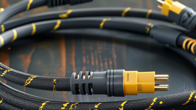
Installation compatibility is easy to overlook. Compare the wire’s outside diameter with clips, grommets, and connector seals, not just its conductor size. Check bend radius near hinges, and leave enough slack for movement without letting the cable rub metal. Crimp samples and inspect for loose strands or damaged insulation. A neat harness can still fail at a tight bend. I would recheck that detail.
| Tip | What to Check | Practical Guidance | Why It Matters |
|---|---|---|---|
| 1 | Conductor material | Prefer copper conductors for typical automotive wiring. Use aluminum or copper-clad aluminum only when the vehicle design and terminals are specifically approved for them. | Conductivity, terminal compatibility, and corrosion behavior depend on the conductor material. |
| 2 | Conductor size | Choose the cross-sectional area or wire gauge using the circuit’s expected current, wire length, allowable voltage drop, installation temperature, and bundling conditions. | A wire that is too small can overheat or cause excessive voltage drop; gauge alone does not determine safe capacity. |
| 3 | Strand construction | Check that the strand count and construction suit the application. Flexible, stranded automotive wire is generally preferable where vibration or movement is expected. | Appropriate flexibility helps reduce conductor fatigue in vehicle environments. |
| 4 | Insulation temperature rating | Compare the wire’s stated continuous temperature rating with the highest expected temperature along its route, including areas near engines or exhaust components. | Excess heat can accelerate insulation aging and increase the risk of electrical faults. |
| 5 | Environmental resistance | Confirm that the insulation is suitable for the expected exposure to oil, fuel, moisture, road chemicals, abrasion, and sunlight where applicable. | Different insulation materials have different resistance to heat, fluids, and physical wear. |
| 6 | Applicable standards | Check the vehicle or equipment specification and the applicable regional cable standard, such as SAE J1128 or ISO 6722 where relevant. Verify the required type and current edition. | Standards define requirements for particular cable applications; one standard or wire type is not automatically suitable for every vehicle. |
| 7 | Terminal and connector compatibility | Match conductor size, strand type, insulation diameter, and terminal design. Use the specified crimp tool and verify the finished connection according to the connector or vehicle instructions. | A correctly sized wire can still fail if the terminal or crimp is incompatible or poorly formed. |
| 8 | Installation route and protection | Plan routing away from sharp edges, moving parts, and high-heat sources. Use suitable grommets, conduit, clips, or abrasion protection where needed. | Good routing and mechanical protection help prevent chafing, short circuits, and damage from vibration. |
| 9 | Fuse and circuit protection | Size the fuse or other overcurrent protection to protect the wire and circuit, following the vehicle design and applicable electrical requirements. | Overcurrent protection helps prevent the wire from overheating if a fault occurs. |
| 10 | Documentation and verification | Check markings, datasheets, traceability, and installation instructions. After installation, inspect the routing and connections and test the circuit as appropriate. | Documented specifications and verification make it easier to confirm suitability and identify installation issues. |