


Top 10 Engine Control System Parts for Global Buyers

Top 10 Engine Control System Parts for Global Buyers

Buying reliable Engine Control System Parts requires more than comparing prices, connector shapes, or delivery promises. Global buyers must assess compatibility, sensor accuracy, software communication, material quality, and long-term supply stability. A throttle position sensor may look identical across two brands, yet its voltage range can differ. One small mismatch can trigger warning lights, unstable idling, or difficult starting.

Dr. John B. Heywood, a leading internal-combustion-engine researcher, has repeatedly stressed the importance of understanding engine systems as connected technologies: “Engine performance depends on the interaction of many subsystems.” That principle guides this list of the Top 10 Engine Control System Parts for Global Buyers. Each component deserves practical attention, from electronic control units and crankshaft sensors to fuel injectors, oxygen sensors, ignition modules, and wiring harnesses.

Fit matters.

So does traceability.

For international purchasing teams, dependable documentation is essential. Product specifications should identify operating temperature, signal type, connector standards, testing procedures, and applicable quality certifications. Suppliers should also explain whether parts are original, aftermarket, remanufactured, or produced under a private label. This distinction is sometimes overlooked. It should not be.

The selection process is not perfectly simple. Catalog data may be incomplete, and regional vehicle variations can create unexpected risks. Buyers should verify part numbers against the engine code and operating environment before placing large orders. The following guide offers a practical starting point, while recognizing that every fleet, distributor, and repair network has different priorities. Reliability begins with careful questions.
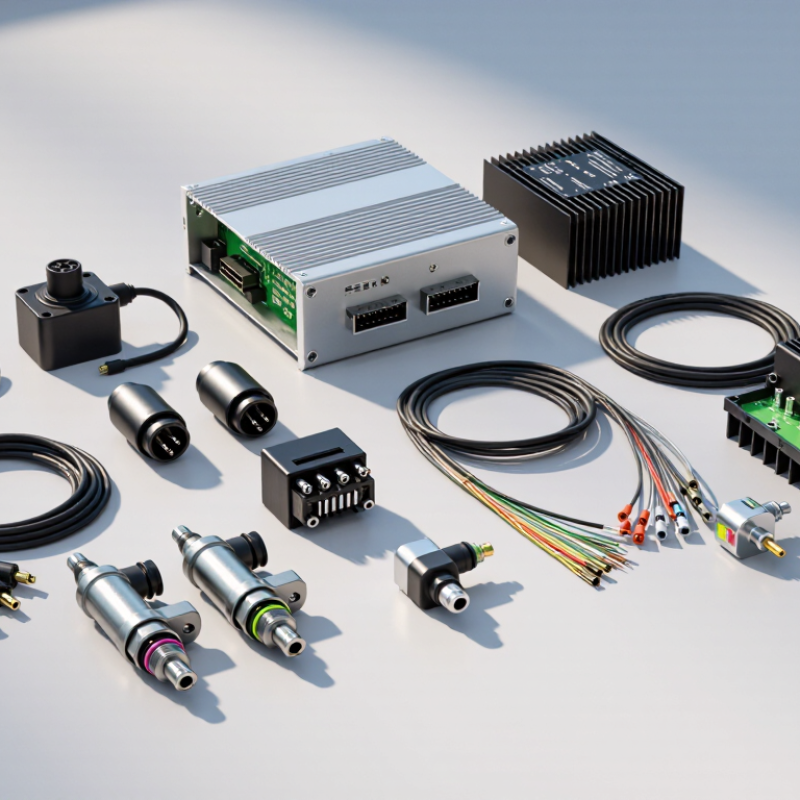
Top 10 Engine Control System Parts for Global Buyers

Engine Control Systems: Definition, Scope, and Core Functions

Top 10 Engine Control System Parts for Global Buyers

Engine control systems are coordinated electronic networks that manage engine performance, emissions, safety, and fuel efficiency. Their scope extends beyond the control unit. It includes sensors, actuators, wiring, communication modules, software, and diagnostic interfaces. Together, these parts interpret operating data and adjust engine behavior within milliseconds.

A control unit processes signals from temperature, pressure, oxygen, speed, and position sensors. It then commands fuel injectors, ignition components, throttle actuators, exhaust valves, and cooling devices. Reliable systems require accurate calibration, stable connectors, and protected wiring. In practical inspections, heat, vibration, moisture, and poor grounding often cause failures before electronic components do. Small details matter.

Global buyers should review voltage compatibility, connector layouts, communication protocols, diagnostic support, and installation records. Regional emission requirements may also change calibration expectations. A useful supplier should provide test data, traceable production information, service guidance, and clear fault-code documentation. Field experience shows that matching a part by appearance alone is risky. It can fit physically but communicate incorrectly. No checklist is perfect. Buyers should verify operating temperature, software compatibility, replacement procedures, and after-sales technical support before procurement. This step feels slow, yet it prevents costly troubleshooting across different markets.

The Top 10 Engine Control System Parts and Their Roles

Top 10 Engine Control System Parts for Global Buyers

The Top 10 Engine Control System Parts and Their Roles

Engine control systems depend on coordinated sensing, timing, fuel delivery, and feedback. In 2023, global vehicle production reached about 93.5 million units, according to the International Organization of Motor Vehicle Manufacturers. That scale makes dependable replacement parts commercially important. The engine control unit, or ECU, processes inputs and commands the system. The crankshaft position sensor measures rotational speed and piston position. The camshaft position sensor confirms valve timing. The mass airflow sensor measures incoming air. The manifold absolute pressure sensor tracks intake pressure. These signals shape injection and ignition decisions.

The throttle position sensor reports driver demand. The coolant temperature sensor helps adjust cold-start enrichment and cooling strategies. The oxygen sensor checks exhaust oxygen levels, supporting closed-loop fuel control. The fuel injector meters pressurized fuel into each cylinder. The ignition coil raises voltage for spark delivery. SAE J1979 standardizes diagnostic data used by many onboard diagnostic systems. This improves testing, but compatibility still requires careful checking.

Real workshop experience shows that sensor faults often resemble fuel or ignition failures. A weak connector can imitate a failed ECU. Heat, vibration, moisture, and poor grounding remain common causes. The U.S. EPA’s Automotive Trends reporting links improved control technologies with continuing efficiency gains, yet laboratory performance can differ from field conditions. Buyers should verify connector design, operating range, calibration requirements, and diagnostic communication. A complete parts list is useful, but it can still mislead without vehicle-specific data.

How Engine Control Components Work Together

An engine control system is a conversation between sensors, software, actuators, and mechanical parts. The engine control unit reads crankshaft and camshaft position sensors, then calculates injection and ignition timing. Mass-airflow or manifold-pressure sensors estimate incoming air. The throttle body regulates it. Fuel pumps and injectors deliver the required quantity, while ignition coils create the spark. Oxygen and nitrogen-oxide sensors check exhaust results. Exhaust-gas-recirculation and turbocharger actuators adjust combustion conditions. One missed signal can disturb the entire chain.

The U.S. EPA’s 2023 Automotive Trends Report recorded an average new-vehicle fuel economy of about 27.1 miles per gallon for model year 2022. It also reported approximately 347 grams of carbon dioxide per mile. These figures show why control accuracy matters, even when the parts appear small. In practice, a weak sensor may cause rich running, hesitation, or a warning light. Yet diagnosis is rarely tidy. A damaged connector can imitate a failed ECU. A dirty throttle can resemble a software fault. Global buyers should check operating temperature, connector protection, calibration support, and diagnostic compatibility. The International Council on Clean Transportation’s real-world studies also show gaps between laboratory and road performance. Laboratory confidence is not enough. Procurement teams should test complete system behavior, not isolated components.

Top 10 Engine Control System Parts for Global Buyers - How Engine Control Components Work Together

No. Engine Control Part Primary Function How It Works With Other Components Typical Input or Output Common Failure Symptoms Maintenance Focus
1 Engine Control Unit (ECU) Processes sensor data and controls fuel injection, ignition, idle speed, emissions functions, and engine protection strategies. Receives data from sensors, applies programmed control logic, and sends commands to injectors, ignition drivers, throttle actuators, and valves. Sensor voltage, frequency, temperature data, actuator duty-cycle commands, and network messages. No-start condition, stalling, poor drivability, warning lamp, or multiple diagnostic trouble codes. Check power, grounds, connectors, software compatibility, and water or heat damage.
2 Crankshaft Position Sensor Reports crankshaft position and rotational speed so the ECU can determine engine timing and synchronization. Works with the camshaft position sensor to identify cylinder position and coordinate injection and ignition events. Variable-frequency pulse signal or digital position signal. Crank-no-start, intermittent stalling, misfire, tachometer drop, or difficult starting. Inspect sensor clearance, wiring, connector condition, and the trigger wheel for damage.
3 Camshaft Position Sensor Identifies camshaft position and helps the ECU determine the operating phase of each cylinder. Complements crankshaft speed data to support sequential fuel injection, variable valve timing, and cylinder identification. Digital pulse or Hall-effect position signal. Extended cranking, reduced power, rough running, misfire codes, or limited variable valve timing. Check timing alignment, oil contamination, harness routing, and connector security.
4 Mass Airflow Sensor Measures the mass of air entering the engine to help calculate the required fuel quantity. Provides airflow data to the ECU, which compares it with throttle position, engine speed, and oxygen feedback. Analog voltage or frequency signal proportional to airflow. Poor acceleration, unstable idle, excessive fuel use, hesitation, or black exhaust smoke. Check for intake leaks, dust contamination, damaged sensing elements, and incorrect air-filter installation.
5 Throttle Position Sensor Measures throttle opening and communicates driver demand or commanded throttle position to the ECU. Works with the accelerator-pedal sensor, airflow sensor, and electronic throttle actuator to regulate engine torque. Redundant variable-voltage position signals. Erratic acceleration, limited throttle response, high or unstable idle, or reduced-power mode. Inspect signal consistency, throttle-body deposits, wiring, and sensor calibration procedures.
6 Engine Coolant Temperature Sensor Measures coolant temperature for cold-start enrichment, cooling-fan control, ignition adjustment, and emissions management. Supplies temperature data used with airflow, oxygen, and engine-speed information to adjust operating strategy. Resistance-based thermistor signal converted to temperature. Hard starting, poor fuel economy, incorrect fan operation, rough idle, or inaccurate temperature readings. Check coolant level, sensor resistance, connector corrosion, and cooling-system leaks.
7 Oxygen or Air-Fuel Ratio Sensor Monitors oxygen content in exhaust gas so the ECU can correct the air-fuel mixture and monitor emissions performance. Provides feedback for closed-loop fuel control and works with fuel injectors, exhaust components, and catalyst monitoring. Voltage, current, or pump-cell signal depending on sensor design. Increased fuel consumption, emissions warning, rough running, or failed emissions testing. Check exhaust leaks, heater circuit, wiring, contamination, and fuel-mixture faults before replacement.
8 Fuel Injector Meters and atomizes fuel into the intake port or combustion chamber according to ECU commands. Responds to ECU pulse width and timing, while fuel pressure and sensor feedback influence the commanded quantity. Electrical pulse-width command and pressurized fuel supply. Misfire, rough idle, hard starting, poor acceleration, fuel odor, or uneven cylinder performance. Check flow balance, spray pattern, coil resistance, fuel contamination, and sealing rings.
9 Ignition Coil Converts low-voltage electrical energy into the high voltage required to create a spark at the plug. Receives timing and dwell commands from the ECU and operates with the crankshaft and camshaft position signals. Low-voltage control signal and high-voltage ignition output. Engine misfire, rough running, reduced power, hard starting, or flashing emissions warning. Inspect insulation, coil boots, spark-plug condition, supply voltage, and heat-related damage.
10 Electronic Throttle Actuator Controls the throttle plate electronically to regulate airflow and engine torque without a direct mechanical cable. Uses ECU commands and redundant position feedback to coordinate driver demand, idle control, traction functions, and safety limits. Motor duty-cycle command and dual position-feedback signals. Reduced power, unstable idle, delayed response, throttle warning, or limited engine speed. Clean approved surfaces, inspect gear and motor operation, and perform required relearn procedures.

Key Selection Criteria for Global Buyers

Top 10 Engine Control System Parts for Global Buyers

Selecting engine control system parts requires more than matching a product photo. The ten common categories include ECUs, crankshaft sensors, camshaft sensors, temperature sensors, pressure sensors, fuel injectors, throttle actuators, ignition modules, wiring harnesses, and relays. Buyers should verify voltage, signal type, connector design, software compatibility, and operating temperature. A part that fits physically may still send inaccurate data. That mistake can cause unstable performance and expensive troubleshooting.

Tips: Request test reports, dimensional drawings, material details, and traceability records. Check whether each part has passed vibration, moisture, heat, and electrical testing. Confirm supply continuity, minimum order quantities, packaging quality, and warranty terms. For international shipments, review labeling and documentation against the destination market’s requirements. Local compliance rules can differ. Never rely only on a supplier’s sales statement.

Field experience shows that sensor accuracy and connector quality are often underestimated. Examine sealing around terminals, especially for vehicles operating near dust or water. Ask how calibration is controlled between production batches. A lower price may hide weaker materials or limited after-sales support. Still, expensive parts are not automatically better. Compare verified evidence, not promises. I would also keep a small trial order before making a large commitment. This step slows purchasing, but it can expose compatibility problems early. Mistakes happen. Good buyers leave room to question their first decision.

Installation, Maintenance, and International Compliance Considerations

Top 10 Engine Control System Parts for Global Buyers: Installation, Maintenance, and International Compliance Considerations

Engine control systems depend on coordinated parts, including sensors, electronic control units, actuators, wiring harnesses, relays, displays, and diagnostic interfaces. Installation should begin with a verified wiring diagram and clean grounding point. A loose terminal can create unstable signals, especially near high-vibration engines. Use connectors with suitable IP protection, and confirm temperature ratings before commissioning.

Maintenance records should capture operating hours, fault codes, calibration dates, and replaced components. This matters because UNCTAD’s Review of Maritime Transport 2023 states that ships carry over 80% of global merchandise trade by volume. Small control failures can therefore interrupt wider supply chains.

The IMO Fourth GHG Study 2020 also estimated shipping produced 2.89% of global anthropogenic greenhouse-gas emissions in 2018. Accurate control data supports fuel efficiency and emissions management.

International buyers should check conformity documents, traceability, electromagnetic compatibility, and hazardous-area requirements where applicable. IEC 60529 helps define enclosure protection, while ISO 9001 supports controlled quality processes. The ISO Survey 2023 recorded more than 1.2 million ISO 9001 certificates worldwide, showing the scale of formal quality management.

Still, a certificate does not guarantee correct installation. Field conditions differ. I have seen technically compliant parts fail after poor grounding and rushed commissioning. That weakness deserves honest review.

Testing should include insulation checks, signal validation, alarm simulation, and a documented restart procedure. Keep spare sensors and connectors sealed, labeled, and climate-controlled.