

How to Choose Armoured Cable in 2026?
Choosing armoured cable in 2026 requires more than comparing prices, conductor sizes, or catalogue photographs. Electricity networks are becoming busier, more distributed, and increasingly exposed to mechanical damage. The International Energy Agency’s Electricity 2024 report forecasts average global electricity-demand growth of 3.2% annually through 2026. That growth places greater pressure on dependable distribution systems. In parallel, IEC 60502-1 remains a key reference for low-voltage power cables, including construction, testing, and performance requirements.
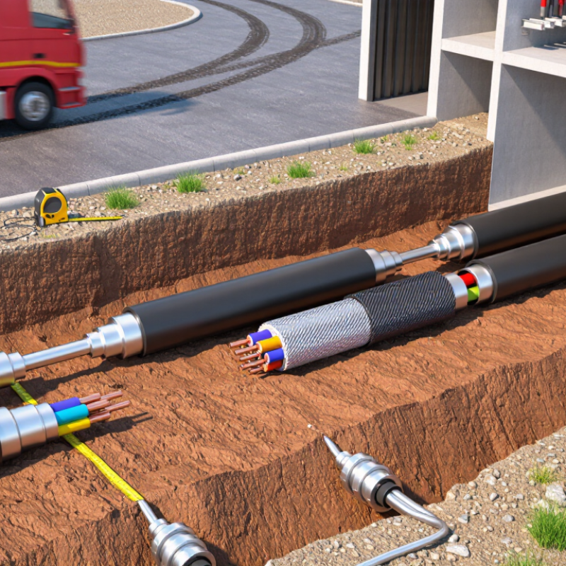
The right selection begins with the installation environment. A cable buried beside a busy access road needs different protection from one inside a dry plant room. Check voltage rating, conductor material, current capacity, fault-current withstand, bending radius, water exposure, soil conditions, and gland compatibility. Steel wire armour may offer strong mechanical protection, while aluminium armour can reduce weight and improve handling. Neither option is automatically better.
George J. Anders, author of Rating of Electric Power Cables, wrote, “The cable rating problem is not a simple one.” His warning remains useful. Armoured cable performance depends on installation details, not only laboratory data. Poor termination can leave a technically excellent cable vulnerable at its ends. That is easy to overlook.
The checklist is not flawless. Temperature, grouping, future load growth, and local workmanship can change the result. Reports and standards guide the decision, but field experience tests it. A reliable 2026 specification should document every assumption, verify certification, and leave room for inspection before energisation. That discipline costs little beside replacing an overheated cable beneath concrete.
Define Armoured Cable Types by Voltage: 0.6/1 kV and 6–30 kV IEC Ratings
How to Choose Armoured Cable in 2026?
Define Armoured Cable Types by Voltage: 0.6/1 kV and 6–30 kV IEC Ratings
Armoured cable selection begins with its voltage designation. For low-voltage systems, 0.6/1 kV cable commonly follows IEC 60502-1. The first figure indicates conductor-to-earth voltage. The second indicates conductor-to-conductor voltage. This detail matters in industrial plants, underground feeders, and outdoor distribution.
Medium-voltage cables usually fall under IEC 60502-2. Typical ratings include 6/10 kV, 8.7/15 kV, 12/20 kV, and 18/30 kV. Do not treat “6–30 kV” as one universal cable rating. The exact U0/U value must match the network design, earthing method, and fault duration. Medium-voltage insulation also needs proper electrical screening and stress control.
Installation conditions can change the correct choice. Check conductor material, insulation type, armour construction, sheath resistance, burial depth, and expected short-circuit current. Steel wire armour may suit mechanical protection, while other armour designs can reduce magnetic effects in specific AC installations. Cable sizing software helps, but measured site conditions remain important. A tidy calculation can still fail if soil thermal resistance is guessed.
Review IEC data, local installation rules, and certified test reports before ordering. Verify bending radius and gland compatibility too. These small details are often missed. A cable that meets voltage requirements may still be unsuitable for moisture, vibration, fire exposure, or repeated movement.
How to Choose Armoured Cable in 2026? - Define Armoured Cable Types by Voltage: 0.6/1 kV and 6–30 kV IEC Ratings
| Voltage Class | Typical IEC Reference | Rated Voltage Designation | Typical Cable Construction | Armour Options | Recommended Installation Areas | Key Selection Considerations |
|---|---|---|---|---|---|---|
| Low voltage | IEC 60502-1 | 0.6/1 kV | Copper or aluminium conductor; XLPE or PVC insulation; metallic screen or filler where required; PVC or other suitable outer sheath. | Steel wire armour Steel tape armour Aluminium wire armour for selected applications | Building services, industrial power distribution, utility networks, outdoor routes, cable trenches and direct-buried systems where permitted. | Confirm conductor material, current-carrying capacity, voltage drop, short-circuit withstand, installation method, minimum bending radius and earthing arrangement. |
| Medium voltage | IEC 60502-2 | 3.6/6 kV to 6/10 kV | Copper or aluminium conductor; XLPE insulation; semiconductive conductor and insulation screens; metallic screen; suitable bedding and oversheath. | Wire armour where specified Non-magnetic armour for single-core cables | Primary distribution feeders, substations, industrial plants, renewable-energy collection systems and medium-voltage motor supplies. | Check screen cross-sectional area, earth-fault current, partial-discharge performance, bonding method, phase arrangement and accessories rated for the same voltage class. |
| Medium voltage | IEC 60502-2 | 8.7/15 kV | XLPE-insulated single-core or three-core cable with semiconductive screens, metallic screen and a mechanically suitable outer sheath. | Metallic wire armour where required Non-magnetic armour for single-core AC circuits | Distribution substations, industrial campuses, data-center utility feeds, transport infrastructure and large commercial facilities. | Evaluate thermal rating under grouped installation, soil thermal resistivity, induced-current effects, screen losses, sheath bonding and fault-clearing time. |
| Medium voltage | IEC 60502-2 | 12/20 kV | XLPE insulation with conductor and insulation screens, metallic screen, bedding and an outer sheath selected for the environment. | Steel wire armour for three-core designs Non-magnetic armour for single-core designs | Utility distribution, industrial substations, mining support systems and medium-voltage infrastructure with elevated mechanical exposure. | Verify insulation level, screen-earth continuity, pulling tension, sidewall pressure, bending radius and compatibility with terminations and joints. |
| Medium voltage | IEC 60502-2 | 18/30 kV | XLPE-insulated cable with controlled electric-field screens, metallic screen and a robust oversheath suitable for the installation environment. | Application-specific wire armour Non-magnetic armour for single-core AC cables | High-voltage distribution feeders, utility substations, heavy industrial sites and long underground power routes. | Confirm system earthing, lightning and switching-surge requirements, screen bonding, allowable pulling forces, thermal conditions and accessory voltage rating. |
| Single-core AC cable | IEC 60502-1 or IEC 60502-2, according to voltage | 0.6/1 kV or 6–30 kV, according to the system | One insulated conductor per cable, normally with conductor and insulation screens for medium-voltage designs. | Aluminium wire armour Other non-magnetic metallic armour | High-current feeders, parallel cable systems, substations and routes requiring individual single-core cables. | Avoid unsuitable magnetic steel armour around single-core AC cables because induced heating and circulating-current losses can occur. Confirm the manufacturer’s installation arrangement and cleat spacing. |
| Three-core cable | IEC 60502-1 or IEC 60502-2, according to voltage | 0.6/1 kV or 6–30 kV, according to the system | Three insulated conductors assembled within one cable, with fillers, bedding, metallic screen or armour and an outer sheath as required. | Galvanized steel wire armour Steel tape armour for suitable LV designs | Compact distribution routes, industrial feeders, underground circuits and installations where a single multicore cable is preferred. | Compare overall diameter, cable weight, bending radius, heat dissipation, installation access and available termination space. |
| Corrosive or wet environment | Applicable IEC 60502 standard plus project environmental requirements | 0.6/1 kV or 6–30 kV, according to the system | Electrical construction selected for the voltage class, with an outer sheath and armour protection appropriate for moisture, chemicals, UV exposure and soil conditions. | Corrosion-protected steel armour Aluminium armour where appropriate | Outdoor cable racks, wastewater facilities, coastal sites, buried routes and industrial areas with chemical exposure. | Specify sheath material, water-resistance features, corrosion protection, UV resistance, drainage, joint sealing and compatibility with the local earthing system. |
Related Posts
-
Why Choose Armoured Cable for Global Projects?
-
How to Choose the Right Armoured Cable for Your Project?
-
Understanding Lead Cables: Essential Insights for Safe Electrical Installations
-
How to Choose the Right Welding Cable for Your Projects?
-

Top Electrical Connectors for Reliable Performance in Your Projects
-
How to Choose the Right Automotive Wire for Your Vehicle?