Why Use a Wire Connector for Electrical Connections?
Why use a wire connector for electrical connections? The answer begins with control, not convenience. A properly selected wire connector joins conductors securely, protects exposed metal, and keeps a splice organized inside an approved enclosure. In practical wiring work, this difference is easy to see. Loose copper can shift under vibration. A correctly fitted connector keeps the connection stable. It can also reduce accidental contact and make future inspection easier. Small details matter.
A wire connector is not a shortcut for careful installation. Its rating should match the conductor size, material, temperature, and intended application. Always follow the manufacturer’s instructions and applicable electrical standards. Experienced installers also inspect the stripped length, conductor position, and connection tension. These checks help prevent overheating, arcing, and unexpected failures. The result is more than a tidy appearance. It is a connection designed to remain dependable over time.
Yet even careful work deserves a second look. A connector may feel tight while a conductor sits incorrectly inside it. That mistake is easy to miss. Different connector designs also require different installation methods, so one technique cannot fit every product. Testing matters. A visual inspection, gentle pull check, and appropriate electrical test can reveal problems before energizing the circuit. When used correctly, a wire connector supports safer, cleaner, and more maintainable electrical connections. It does not replace knowledge. It makes good workmanship more consistent.
What a Wire Connector Is and How It Joins Electrical Conductors
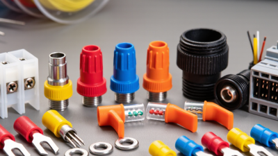
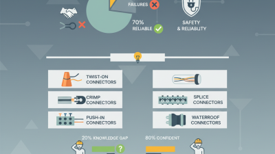
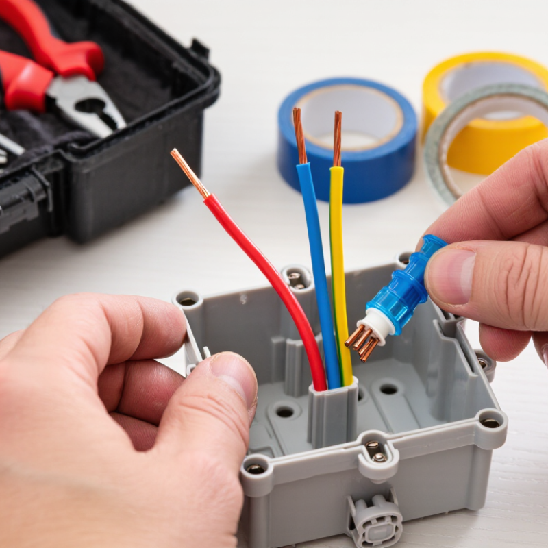
A wire connector is a small device that joins two or more electrical conductors safely. It creates a firm electrical path while helping prevent exposed metal, loose strands, and accidental contact. Common types include twist-on connectors, push-in connectors, crimp terminals, and lever-style connectors. Each design works with specific conductor sizes and materials.
The joining process begins with preparation. Turn off the circuit, then verify that no voltage remains. Remove only the required insulation length. Too little exposed copper may weaken the connection. Too much can leave dangerous metal outside the connector. Insert the conductors fully, following the connector’s instructions. With a twist-on type, the conductors should remain aligned while the connector tightens. A gentle pull test can reveal a loose wire.
Details matter.
In practical electrical work, many failures start with poor preparation rather than a defective connector. A connector rated for solid copper may not suit stranded wire or mixed metals. The connector must also match the wire size and the number of conductors. Moisture, vibration, and heat can affect performance, especially inside crowded boxes or outdoor enclosures. I have found that a neat appearance is not proof of a reliable joint. Rechecking the strip length and conductor placement takes little time. However, manufacturer instructions and local electrical requirements should always guide the installation. When uncertainty remains, a qualified electrician should inspect the connection.
Why Use a Wire Connector for Electrical Connections?
A wire connector joins electrical conductors into a secure, insulated, low-resistance connection. The chart below shows how conductor size affects the resistance of annealed copper wire at 20°C, helping explain why a connector must match the wire size and connection requirements.
Key point: Larger copper conductors have lower resistance. A properly selected wire connector keeps the conductors firmly joined and maintains a reliable electrical path without exposing the connection to accidental contact.
Reference basis: typical DC resistance values for annealed copper conductors at 20°C, expressed per 100 meters.
How Wire Connectors Improve Safety and Connection Reliability
Wire connectors improve electrical safety by making conductor joints secure, insulated, and easier to inspect. A properly selected connector helps prevent exposed copper, accidental contact, and movement caused by vibration. It also maintains steady pressure between conductors. That matters because loose connections can create resistance, heat, and eventually insulation damage.
The National Fire Protection Association reported an annual average of 32,620 U.S. home fires involving electrical distribution and lighting equipment from 2015 to 2019. These fires caused approximately 470 civilian deaths, 1,100 injuries, and $1.3 billion in direct property damage. A connector cannot prevent every failure. However, it can reduce common installation weaknesses when its wire range, temperature rating, and current capacity match the circuit. Guidance in NFPA 70 and IEC 60999 also emphasizes suitable terminals and reliable conductor retention. In practical work, the connection should feel firm, not merely look finished. Even experienced installers can miss a partially inserted wire.
Tips: Turn off power and verify it with a suitable tester. Strip only the specified insulation length. Insert every conductor fully, then perform a gentle pull test. Avoid mixing wire sizes unless the connector permits it. Keep copper free from oil, moisture, and deep tool marks. A connector may seem oversized, but cramped boxes can stress it and reduce reliability. Inspect the finished joint again; that small pause is easy to skip.
Key Types of Wire Connectors and Their Suitable Applications
Why Use a Wire Connector for Electrical Connections?
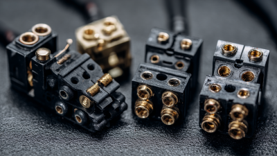
Wire connectors create secure electrical contact while protecting exposed conductors from accidental contact, moisture, and mechanical stress. The correct type depends on wire size, material, current, and installation conditions. A connector should never be selected by appearance alone.
Twist-on connectors work well for compact, dry indoor junction boxes. They are useful when several solid or stranded wires must be joined quickly.
Push-in connectors suit tidy installations with compatible wire sizes and limited movement. However, poor insertion can leave a loose conductor. That mistake is easy to miss.
Lever connectors handle mixed wire types and allow later inspection, making them practical for lighting repairs and control cabinets.
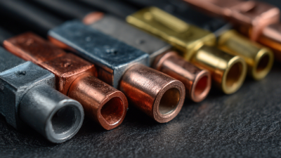
Crimp connectors provide strong connections when paired with the correct terminal and crimping tool. They are common in vehicles, machinery, and areas exposed to vibration. Heat-shrink crimp connectors add insulation and improved moisture resistance. For outdoor or damp locations, gel-filled connectors offer additional protection, but they still require suitable enclosures. Terminal blocks are better for organized panels, where each circuit needs clear identification and testing access.
During installation, strip only the required insulation length. Exposed copper should not extend beyond the connector. Pull-test each completed connection gently. It should not move.
Wire connectors are not universal, and local electrical codes may limit their use. Checking the manufacturer’s specifications and measuring the conductor accurately prevents many avoidable failures. My own preference is to leave enough space for inspection, although crowded boxes remain a common practical compromise.
Steps for Installing and Inspecting a Wire Connector
A wire connector creates a stable electrical and mechanical joint when installed correctly. NFPA’s Home Structure Fires report found electrical distribution and lighting equipment involved in about 24% of reported home fires from 2016 to 2020. Poor connections can produce resistance, heat, and insulation damage.
Begin by switching off the circuit and verifying dead wires with a properly rated tester. Never trust the breaker position alone. Select a connector matching the conductor material, size, and number of wires. Check the manufacturer’s approved wire range before stripping insulation. Remove only the required length. Exposed copper should not extend beyond the connector.
Insert the conductors fully and tighten the connector according to its instructions. Do not force damaged or uneven wires into place. Give each conductor a firm tug. A loose wire may pass a quick visual inspection. That is where many installation errors begin. Fold the conductors carefully into the electrical box without sharp bends. Ensure the connector remains secure and accessible for inspection.
Inspect completed connections for exposed copper, cracked insulation, corrosion, discoloration, or melting. Warmth, buzzing, or a burnt smell requires immediate isolation and professional evaluation. NFPA 70B emphasizes documented electrical maintenance and condition-based inspection for safer systems. I still recheck connections after the circuit carries its normal load. It may seem excessive. Small defects can worsen quietly, especially in vibrating equipment or crowded boxes. A clear inspection record also helps identify repeated failures, incorrect conductor combinations, or workmanship that needs improvement.